What to look out for in PV systems:
AC side
Test all AC circuits to the requirements of IS10101 Chapter 6.
DC Side
Are you carrying out these DC tests?
Test all DC circuits to the requirements of IS10101 Chapter 7 (clause 712.6.101) and I.S. EN 62446 gives additional requirements for system documentation, commissioning tests and inspection.
- Continuity of earthing and/or equipotential bonding conductors, where fitted
- Polarity test
- Combiner box test
- String open circuit voltage test
- String circuit current test (Short circuit or operational)
- Functional tests
- Insulation resistance of DC circuits
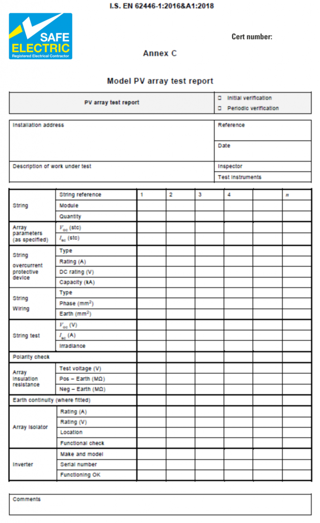
According to rule 712.6.101 (Page 592 I.S. 10101 2020) Grid Connected PV systems must be subject to additional commissioning tests and inspection as outlined in I.S. E.N. 62446. These additional tests are primarily on the DC side of the PV installation. The tests include, insulation resistance of the DC cables, measurement of the current being produced from the P.V. strings when they are subject to a short circuit and the voltage when the strings are open circuit. It is also a requirement to verify the string voltage when it is connected to the inverter. The results of these tests are required to be recorded on a form which has been reproduced by SEAI for grant purposes.
The EN standard requires that these values are obtained by test and measurement and calculating the expected values using values provided by the manufacturer is not complying with the standard. These tests can be done with standard off the shelf test equipment and there are also some specialised meters which make the testing easier and safer. It is also necessary that the RECs has in their possession the correct leads to connect into the PV arrays to correctly and safely test the system.
The tests must be carried out by the Qualified Certifier (QC) for the Registered Electrical Contractor who has carried out the work.
To carry out the short circuit test, the string is disconnected by dropping out the shunt or opening the DC isolator and the + and – of the string are shorted out. The circuit is then closed and using either a DC clamp meter or a suitable multimeter connected in series with the string, a measurement of the current being produced by the string is obtained. This measurement must then be compared with the expected output of the strings as provided by the manufacturer.
The problem is that the only time the string will produce its full output current is when it is subject to full sunlight, and this may not be the case on the day the tests are carried out.
To overcome this issue the level of light that the panels are being subject to at the time of the test, can be measured using an Irradiance Meter and a correction calculation is applied. This then gives the calculated true value which can be recorded on the documentation.
To carry-out the open circuit voltage test, the strings are disconnected from the inverter and the voltage measured across + and – to ensure the expected voltage is present. For example, if there are 10 panels in the string, and each panel outputs 38 volts, then the expected voltage would be 380 volts. This value is also affected by the light levels but not as much as the amps value.
This test is important as it confirms that all the panels have been included in the string. If some of the PV Panels have been inadvertently bypassed, it would be identified because the measured voltage would be lower than expected.
There is also a requirement to carry out an insulation resistance test between the DC cables, the conductive frames on the roof, and/or earth. This test should be done by disconnecting the string by dropping out the shunt or opening the DC isolator and shorting out the + and –. The circuit is then closed and an I.R. test is carried out between the shorted + and – of the string and the frames supporting the PV array and/or earth. This test is important as it is possible that cables from the panels can get pinched between the frames or that a faulty panel can apply DC voltage to earth.
During inspections of Photovoltaic installations, Safe Electric will ensure that as well as having the normal test equipment to carry out the tests required by I.S. 10101, RECs have in their possession test equipment that can do the following:
- Measure DC current, either a DC clamp meter or a multimeter which can be connected in series with a suitable DC amps range
- Measure DC voltage, some multi-function meters only measure AC voltage
- Measure Insulation Resistance at twice the expected DC voltage, could be up to 1000 volts
- Optional – Irradiance meter
All RECs installing PV systems should note that it is a requirement that the Qualified Certifier (QC) who carried out the DC testing records the results on the enclosed Annex C (model PV array test report), see example below. While also noting a standard Test Record Sheet (TRS) will be required to be produced for the AC circuit(s).
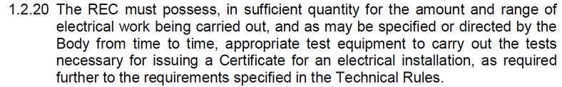
During Inspections, if it is identified that these tests have not been correctly done, this will be recorded as a Non-Conformance with rule 712.6.101 on the report. Safe Electric Inspectors will also check that RECs are in compliance with Clauses 1.2.10 and 1.2.20 (Page 65 & 68) of the CRU Electrical Criteria Document and have sufficient Qualified Certifiers and Test Equipment to cater for the scope of work they are certifying.
Resource Requirements
It is imperative that all RECs adhere to the criteria document and in particular rules 1.2.10 & 1.2.20 where RECs are required to have suitable number(s) of QCs for workload and geographical spread.
See extracts from pages 65 and 68 of the Criteria Document:

See below a sample of Annex C form from the EN standard: